Airplanes have been in commercial use for a long time, yet misconceptions about how they fly remain common. In this article, I take a non-specialist’s perspective—although I did study the subject as an undergraduate—to briefly explore how aerodynamic lift is understood.
The basic idea is that air passing a wing moving horizontally does not simply continue horizontally: the air gains a net downward momentum, while the wing experiences an upward force. We can describe this phenomenon through pressure, energy, momentum, and circulation, and will look at each perspective in turn.
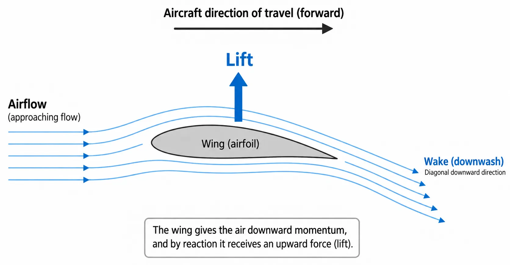
When a wing gives air downward momentum, the wing experiences a force in the opposite direction. Lift and drag are the components of the aerodynamic force perpendicular and parallel to the freestream, respectively. The vertical and horizontal components of wake velocity are not themselves lift and drag. Calculating the actual force requires considering pressure and momentum flow around the wing together.
1. Bernoulli’s Principle: A Frequent Source of Misconceptions
One of the most common incorrect explanations of lift is illustrated below. Air arriving at the front of the wing splits into upper and lower streams, and the explanation assumes that both must reach the rear at the same time regardless of their path lengths. If the upper path is longer, the argument goes, air along it must move faster.
Sometimes this is accompanied by another claim: faster air above the wing must have a lower density, which lowers its pressure relative to the air below and creates an upward force. However, the low-speed flows discussed here can be treated as having nearly constant density while still explaining lift. Equating faster flow with lower density is also inaccurate.
There is no reason why air parcels that split at the front of the wing must reunite at the rear, and experiments confirm that they do not arrive together. This explanation is therefore incorrect. Where did the misconception come from?
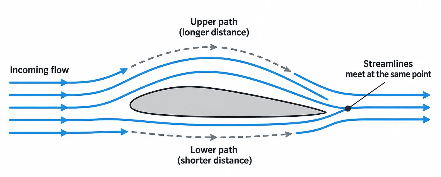
This diagram is commonly used to argue that air must move faster because the upper path is longer. Adding the assumption that upper and lower air parcels must meet again at the rear produces an incorrect lift model. The arrows do not represent travel times or actual velocity magnitudes. “Incorrect model” refers to this explanation, not to Bernoulli’s equation itself.
Bernoulli’s Equation
Bernoulli’s equation uses energy conservation to describe the relationship between a flowing fluid’s pressure, speed, and elevation. Accelerating a fluid or raising it to a greater height requires energy. If no energy is supplied from outside and there are no losses, that increase must be balanced by a decrease in another term, such as the energy associated with pressure.
For example, flow accelerates through a narrow section of a horizontal pipe, increasing its kinetic energy while lowering its static pressure. Conversely, if a fluid rises to a greater elevation at the same speed, its potential energy increases while its static pressure decreases. The key is to consider pressure, speed, and elevation together through the conservation of their combined energy terms.
For steady, incompressible flow, neglecting viscous losses and energy transfer through pumps or turbines, the relation along a streamline is:
is static pressure, is density, is flow speed, is gravitational acceleration, and is elevation above a reference level. The three terms represent pressure work, kinetic energy, and potential energy per unit volume, all with units of Pa. This relation does not allow us to compare the pressures of unrelated flows using speed alone.
What Is Dynamic Pressure?
The middle term, , is dynamic pressure. It expresses the flow’s kinetic energy in pressure units; it does not mean that an additional pressure acts independently in every direction on top of static pressure. At constant density, doubling the speed quadruples dynamic pressure.
If incompressible flow is brought to rest without losses at the same elevation, its stagnation pressure is . Under those conditions, the difference between stagnation and static pressure is dynamic pressure. NASA Glenn — Dynamic Pressure.
What Happens in a Venturi Tube?
When water fills a pipe and flows without leaking or accumulating, the flow rate is the same at every cross-section.
At the same flow rate, a smaller cross-sectional area means a higher speed. At the narrow throat of a horizontal Venturi tube, speed and dynamic pressure increase while static pressure decreases. The liquid column in a vertical tube measuring static pressure therefore falls. Pressure recovers as the pipe widens again, but actual losses prevent complete recovery to its initial value.
Dividing Bernoulli’s equation by lets us compare all three terms as heights, or heads.
| Term | Meaning as a height |
|---|---|
| Pressure head | Height of a column of the same fluid that balances the pressure |
| Velocity head | Kinetic energy expressed as an equivalent height |
| Elevation head | Height of the measurement point above the reference level |
The line representing pressure head plus elevation head is the HGL (hydraulic grade line). The line representing all three terms is the EGL (energy grade line). Their separation is the velocity head. Without losses, the EGL remains constant; with losses, it falls in the flow direction. USBR — Energy Balance and Head.
Explore the Interactive Venturi Tube →
Reduce the throat diameter and compare flow speed with the liquid-column height. Next, raise the outlet while keeping the flow rate and diameters unchanged. Speed stays the same, while pressure head decreases by the increase in elevation head. The Pressure and Head views show the same relationship in different units.
Where Does the Misconception About Wing Flow Begin?
Returning to the wing: in steady, incompressible flow through a Venturi tube, the volumetric flow rate remains constant at every cross-section. Narrowing the pipe therefore increases speed and, through Bernoulli’s equation, lowers static pressure. This principle has often been applied directly to wings: the curved upper surface supposedly narrows the flow passage, making air move faster and lowering pressure.
However, a wing has no fixed upper wall confining the flow as a Venturi tube does. A curved upper surface alone does not establish a reduced flow area or a higher speed. The actual velocity and pressure distributions depend on wing shape, angle of attack, circulation, and interactions throughout the surrounding flow field. Bernoulli’s equation is not the problem; the inaccurate explanation of why air speeds up is.
Explaining Lift with Bernoulli’s Equation
The failure of those explanations does not mean that using Bernoulli’s equation to explain lift is wrong. The equation plays an important role in understanding pressure distributions and lift around a wing.
As a wing moves through air, its shape and angle of attack help establish the surrounding flow field. Under typical lifting conditions, air above the wing accelerates, while the lower flow is relatively slower. These velocity distributions are closely linked to the pressure distribution.
For steady, incompressible, inviscid flow along a streamline, Bernoulli’s equation relates increasing speed to decreasing static pressure. Regions of accelerated flow above the wing therefore have lower pressure, and differences in pressure around the wing produce aerodynamic forces. Under ordinary flight conditions, the low pressure above the wing makes a substantial contribution to lift.
The important limitation is that Bernoulli’s equation alone cannot determine the velocity distribution around a wing. Explaining the faster upper flow also requires the wing’s geometry, angle of attack, circulation, and flow boundary conditions. Bernoulli’s equation describes how speed and pressure are related within the resulting flow field.
Lift can also be understood through the change in the air’s momentum. The pressure distribution changes the airflow, giving the air a net downward momentum as it passes the wing. As the air gains downward momentum, the wing experiences a force in the opposite direction.
The pressure explanation using Bernoulli’s equation and the downwash explanation using Newton’s momentum conservation are not competing theories. They describe the same aerodynamic phenomenon from the perspectives of pressure and momentum.
The following sections introduce other useful concepts. Keep in mind that they describe different aspects of the same flow rather than adding separate contributions to lift.
2. The Magnus Effect: Why Does a Spinning Ball Curve?
How Are Bernoulli’s Equation and the Magnus Effect Connected?
The Magnus effect is the transverse force experienced by a rotating body in a fluid flowing relative to it. A spinning ball following a curved trajectory is a familiar example. Rotation is a condition that helps produce the force; a velocity difference tending to rotate a body is not what the term “Magnus effect” means.
Bernoulli’s equation and the Magnus effect answer different questions.
| Comparison | Bernoulli’s equation | Magnus effect |
|---|---|---|
| Main question | How are pressure, speed, and elevation related? | Why does a rotating body experience a force across the flow? |
| Body rotation | Not required. | A defining condition. |
| What it describes | Fluid energy conservation under specified conditions. | Rotation changing the surrounding flow and producing a transverse force. |
| Connection | Relates speed and pressure where its assumptions apply in the established flow. | Establishing that flow involves viscosity, boundary layers, and separation. |
For a spinning ball, surface rotation influences the surrounding flow, establishing an asymmetric pressure distribution and a force that curves its trajectory. Boundary layers, separation, and surface roughness also affect the actual force. The Bernoulli relation connects speed and pressure but does not explain the entire process by which rotation establishes the flow. NASA Glenn — Lift of a Baseball.
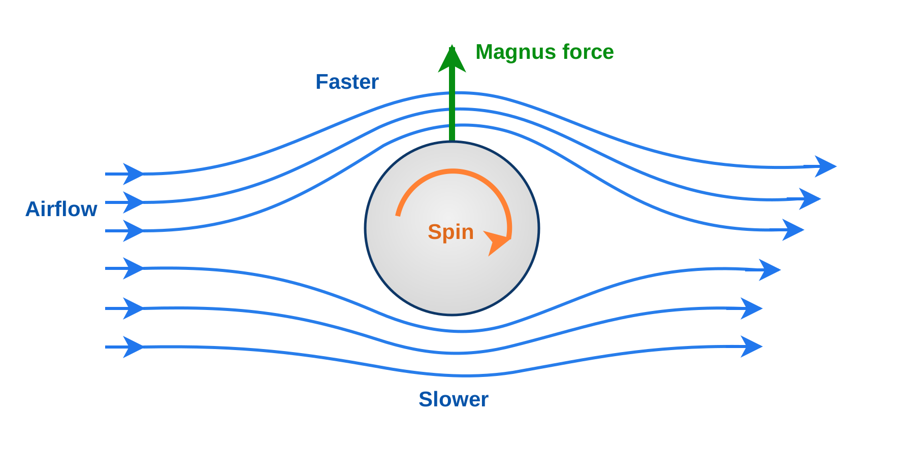
A conceptual diagram of the Magnus force on a rotating cylinder. Blue lines are streamlines, the orange arrow shows cylinder rotation, and the green arrow shows the Magnus force under these conditions.
In the diagram, air flows from left to right and the cylinder rotates clockwise. Above the cylinder, the rotation-induced flow reinforces the main flow—the surface moves in the same direction as the airflow—so the flow is shown as relatively fast. Below the cylinder, the directions oppose each other, so the flow is shown as relatively slow.
If the idealized upper and lower flows share the same stagnation pressure, Bernoulli’s relation gives a lower static pressure in the faster upper flow. Integrating the asymmetric pressure distribution over the cylinder surface gives an upward force in this example. This does not mean that pressure rises because air continually accumulates below the cylinder.
This is a simplified rotating-cylinder diagram, not a prediction of the actual streamlines or force magnitude around a spinning ball. Real flows involve viscosity, boundary layers, and separation. NASA Glenn — Lift of a Rotating Cylinder.
Is Wing Lift Also a Magnus Effect?
A conventional fixed wing can change the surrounding flow and generate lift through its shape and angle of attack without rotating. Its lift is therefore not called the Magnus effect. Both cases do involve asymmetric flow and pressure distributions. In idealized two-dimensional models, a rotating cylinder and a wing can be connected through the common concept of circulation. Circulation is a property of the flow, not rotation of the body itself.
A wing can also experience a pitching moment that tends to change its orientation. Depending on where surface forces act relative to a reference point, they can tend to raise or lower the nose. An aerodynamic force tending to pitch a wing is a pitching moment; a rotating body experiencing a transverse force in a flow is the Magnus effect.
With that distinction in mind, let us consider how a wing changes the flow without rotating.
3. Why Does Air Change Direction Around a Wing?
Bernoulli’s equation relates speed and pressure, but Newton’s second law offers a useful way to understand a change in flow direction. Even at constant speed, a change in direction is an acceleration. Air following a curved path therefore requires a force.
Pressure Differences Along and Across the Flow
Outside the boundary layer, neglecting viscosity and gravity, this force comes mainly from pressure differences in the surrounding air. If the rear of a small air parcel experiences a higher pressure than its front, the net force accelerates it forward. The change in pressure along the flow is a pressure gradient. For steady flow:
is distance along a streamline, and is the local speed. A pressure decrease in the flow direction makes negative, so speed increases. Integrating this relation at constant density gives the Bernoulli relation in Section 1. Faster flow and lower pressure can be understood through the forces on an air parcel as well as energy conservation. Babinsky — How Do Wings Work?.
The pressure difference that turns the flow acts in a different direction. Curving air requires an acceleration toward the center of curvature. If measures distance outward from that center, then:
is the local radius of curvature of the streamline, not the wing surface. Higher pressure outside pushes more strongly than lower pressure inside, turning the air. At the same speed, a tighter turn requires a larger pressure gradient. This relation alone does not determine the entire wing’s velocity or pressure field. MIT — Streamline Curvature and Lift Generation.
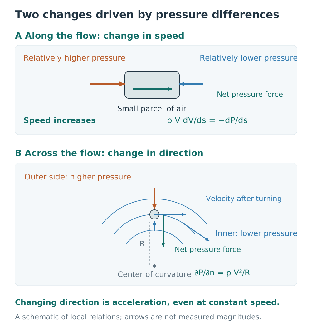
Orange and blue arrows show pressure forces from opposite sides; green arrows show the net force. In the lower panel, horizontal and inclined blue arrows show velocity directions at different positions. Pressure forces can change both speed and direction. This is a schematic: arrow lengths do not provide measured pressures or forces.
How Does the Whole Pressure Distribution Produce Lift?
It is difficult to separate this into a one-way sequence such as “the wing first turns the air, then the pressure falls.” Air cannot pass through the wing, and the incoming flow far away has a prescribed direction and speed. The pressure and velocity fields are determined together to satisfy those conditions and conservation of mass and momentum. The Euler equations describe flow neglecting viscosity; the Navier–Stokes equations include viscosity. NASA Glenn — Bernoulli and Newton.
A wing does more than push air with its lower surface. Both upper and lower surfaces turn the flow, and pressure influences extend into the surrounding air. Adding the pressure forces over the entire surface and taking the component perpendicular to the incoming freestream gives lift. Viscous shear forces also act on a real surface, but an ordinary wing’s lift is determined mainly by its pressure distribution. NASA Glenn — What Is Lift?.
The following example is computed directly for the Joukowski airfoil introduced in Section 4. The streamlines and pressure distribution show the direction, speed, and pressure of the same flow. Colors and curves use the pressure coefficient, which divides the difference from freestream static pressure by freestream dynamic pressure:
Negative means pressure below the freestream value; positive means pressure above it. A negative pressure coefficient does not mean negative absolute pressure. Compare the distribution and force directions over the entire surface rather than pressure at just one point. Parts of the lower surface can also be below freestream pressure. University of Sydney — Surface Pressure Distribution and Lift.
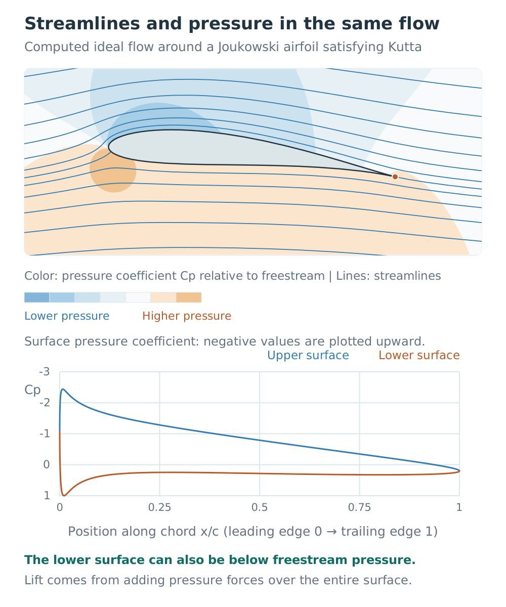
The upper panel shows pressure-coefficient colors and streamlines in two-dimensional ideal flow. The lower panel shows surface pressure coefficients for the same solution, with negative values plotted upward as customary in aerodynamics. In this example, much of the upper surface is at low pressure, while the lower surface also falls below freestream pressure near the trailing edge. Boundary layers, stall, and wingtip effects are excluded. The trailing-edge condition and circulation are explained in the next section.
How Is Downwash Connected to Surface Pressure?
Pressure around a wing both exerts forces on the wing and changes the air’s momentum. Summing surface pressure forces and evaluating the momentum balance of the surrounding air therefore give the same force. What matters is momentum flow throughout the affected air, not merely the inclination of one arbitrarily chosen streamline.
A control surface enclosing the air requires accounting for both incoming and outgoing momentum and pressure forces on that surface. An explanation based only on air striking the lower surface and bouncing downward omits the upper surface and the surrounding flow. NASA Glenn — Lift from Flow Turning.
Does the Coandă Effect Hold Air Against the Wing?
The Coandă effect describes a jet tending to remain attached to a nearby surface. A circulation-control wing can blow a jet along a curved surface, changing jet direction and separation location to control circulation and lift. This is a real lift-enhancement technique, but it does not mean every wing requires a separate “attachment force.” NASA — Noise Reduction through Circulation Control.
Even if this name is applied to flow following an ordinary wing, it does not by itself determine velocity, pressure, or lift. Those still require pressure gradients, boundary conditions, and the boundary-layer and separation behavior discussed in Section 5. No law requires flow always to remain attached; extensive separation changes the wing’s performance.
4. Circulation and the Kutta Condition: Why Is There Circulation if the Wing Does Not Rotate?
Circulation, introduced in the Magnus-effect discussion, is the integral of the tangential velocity component around a closed path enclosing a body. It is written and has units of . It does not mean that air parcels continually orbit the wing or that the wing rotates.
Potential Flow: A Starting Point for Calculating Wing Flow
Earlier, we said that the surrounding velocity and pressure fields are determined together. How can we calculate that velocity field? One approach approximates the flow outside the boundary layer as incompressible, irrotational ideal flow. “Irrotational” means that vorticity—the measure of a small fluid element’s rotation about its own center—is zero. The velocity can then be expressed through a function called a velocity potential, giving the name potential flow. University of York Lecture — Velocity Potential and Complex Potential.
In potential flow, simple solutions can be added together to construct more complex flows. For example, adding a circulation flow to the flow around a circle describes the outer flow of the rotating cylinder discussed in Section 2. Circulation here is a mathematical term describing an established flow, not a claim that an inviscid cylinder can drag the surrounding air into rotation. Viscosity participates in establishing circulation around a real rotating cylinder.
“Irrotational flow with circulation” may sound contradictory, but local rotation of a small fluid element and circulation around a larger path are different quantities. The interior of a wing or cylinder is excluded from the outer flow domain. Consequently, the exterior flow can have zero vorticity while a path enclosing the body has nonzero circulation. University of York Lecture — Circulation and the Magnus Effect.
The Kutta Condition: Which Circulation Should We Choose?
The requirement that air cannot pass through the wing, together with the prescribed flow far away, does not uniquely determine circulation. Ideal-flow solutions can satisfy the same geometry and incoming conditions while having different circulations. Saying “adding circulation produces lift” therefore leaves a question unanswered: which circulation is established around the actual wing?
We add the Kutta condition: flow must leave the sharp trailing edge smoothly at a finite speed, rather than accelerating without bound or turning abruptly around the edge. Selecting the circulation that satisfies this condition changes the velocity distribution around the entire wing, not just near the trailing edge. The condition does not require upper and lower air parcels to arrive simultaneously. MIT OpenCourseWare — Kutta Condition.
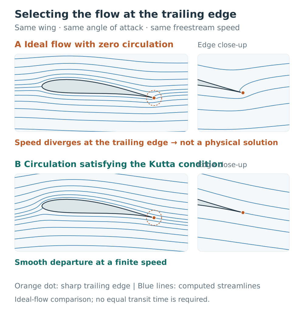
Two-dimensional ideal flows computed directly for the same geometry and incoming conditions. The upper case has zero circulation; the lower case uses circulation selected by the Kutta condition. Orange dots mark the trailing edge, enlarged on the right. The divergent speed in the upper solution cannot be measured from this streamline drawing alone; it is a property identified through the velocity transformation equation below. Blue lines are streamlines, not particle travel-time markers. The freestream runs from left to right.
As a real wing starts moving, viscosity and the starting vortex shed near the trailing edge help establish circulation. Circulation around the wing and the starting vortex have opposite directions. The Kutta condition is not a new force that creates circulation; it incorporates the actual flow’s trailing-edge behavior into an ideal-flow calculation. It does not calculate all boundary-layer behavior or stall. MIT — Lifting Surfaces.
Kelvin’s circulation theorem also helps explain this connection. For constant-density flow with negligible viscosity and only conservative body forces, circulation around a closed path moving with the fluid is conserved. A path enclosing both the wing and the starting vortex helps explain their opposing circulations. The theorem should not be applied unchanged near the viscous wing surface to claim that circulation appears spontaneously. MIT — Formation of Lifting Flow.
The Joukowski Transformation: How Do We Map a Circle’s Solution to a Wing?
The Joukowski transformation provides a mathematical connection between the Magnus-effect cylinder and a wing. It maps the relatively simple flow around a circle to flow around an airfoil with a rounded leading edge and a sharp trailing edge. Representing a point in the circle plane by the complex number , its image in the airfoil plane is:
is a length scale; and also have units of length. Nondimensionalizing so that gives the familiar form . Choosing the circle’s center and radius appropriately produces an airfoil with thickness and camber. The surrounding flow solution must be mapped along with the body’s outline. This is what distinguishes the method from simply reshaping a drawing. NASA Glenn — Conformal Mapping.
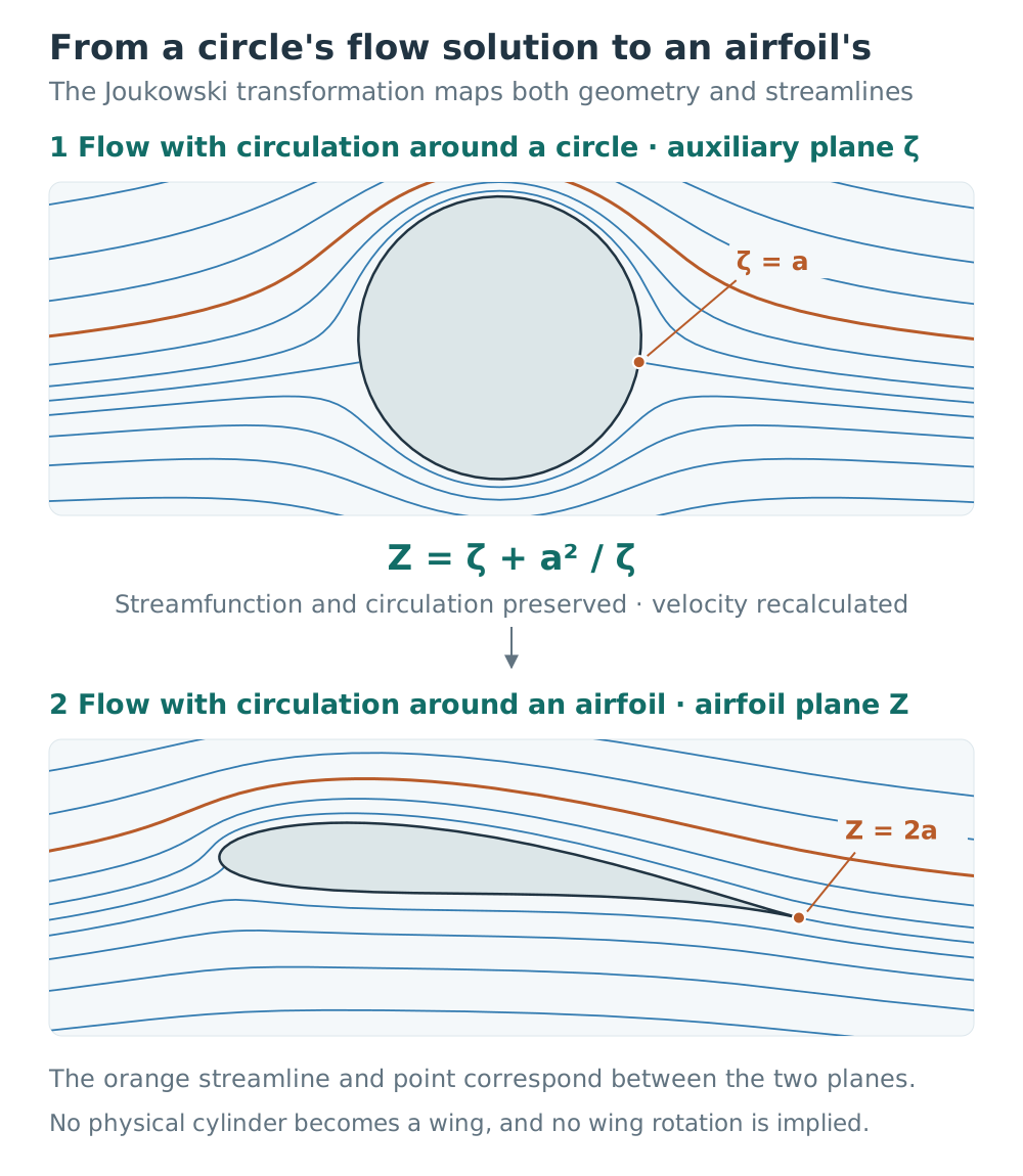
The upper panel shows streamlines calculated from the circle’s complex potential; the lower panel applies the Joukowski transformation to each point. The orange curves are corresponding versions of the same streamline, and the orange point on the circle maps to the airfoil’s trailing edge. These are solutions in different coordinate planes, not a physical cylinder changing into a wing. The circle has no arrow suggesting that the body itself must rotate.
Conformal mapping preserves the angles between infinitesimal lines where the mapping is smooth and its derivative is nonzero. It does not preserve lengths, areas, or speeds unchanged. The airfoil’s velocity field must be recalculated according to how the mapping locally stretches or contracts the coordinates, rather than copied directly from the circle’s velocity field.
Writing the complex potential as , the relation is as follows. In the complex velocity , and are the horizontal and vertical velocity components.
At , the point corresponding to the trailing edge, the denominator is zero. If the numerator remains nonzero, the calculated speed becomes infinite. Choosing circulation to satisfy the Kutta condition makes the numerator vanish there too, giving a finite limiting velocity. In this example, the physical requirement of smooth departure from the trailing edge becomes the mathematical requirement of removing the velocity singularity. Because the Joukowski transformation creates a cusp at the trailing edge, the general angle-preservation statement does not apply unchanged at that point. University of York Lecture — Conformal Mappings and Joukowski Mapping.
The Kutta–Joukowski Theorem: From Circulation to Lift
For steady, incompressible, two-dimensional ideal flow, the Kutta–Joukowski theorem gives the magnitude of lift per unit span from circulation:
is lift per unit span (), and is the freestream speed before the wing disturbs the flow. The force direction depends on the circulation direction. The Joukowski transformation is a method for finding the flow; the Kutta–Joukowski theorem is a relation for finding force from circulation. Despite their similar names, they have different roles. The lift theorem does not require the airfoil itself to have been constructed with a Joukowski transformation. University of York Lecture — Kutta–Joukowski Lift Theorem.
For the outer flow at the same elevation, Bernoulli’s equation connects the calculated local speed to pressure:
is the freestream static pressure. We can therefore use the selected circulation to calculate velocity, obtain pressure from this equation, and sum the surface pressure forces to calculate lift. The result agrees with the Kutta–Joukowski theorem. Circulation does not generate an additional force on top of the pressure forces. When making this article’s streamline figures, I also checked that numerically integrating surface pressure gives the same lift as the circulation calculation.
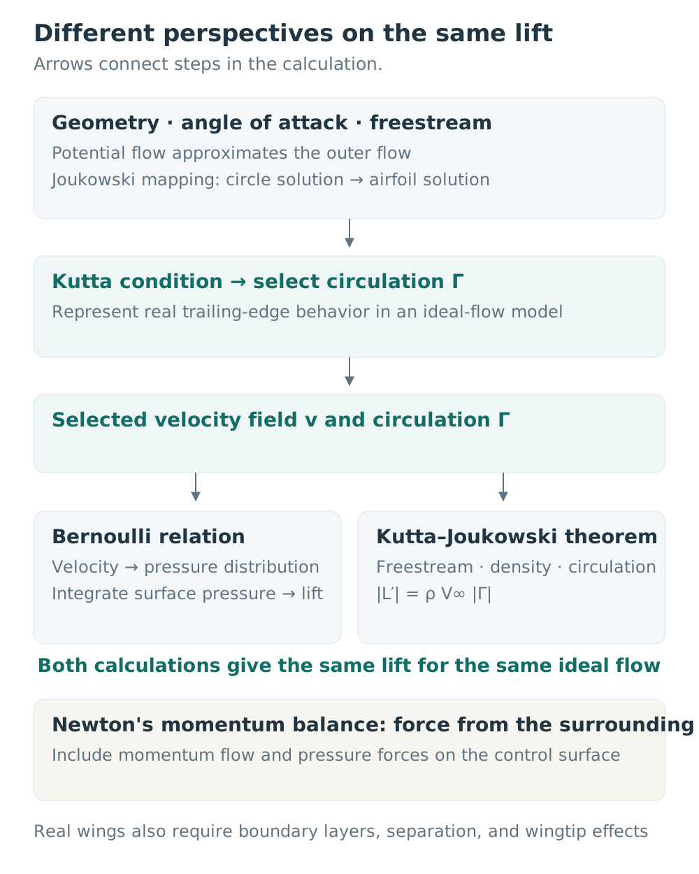
An original diagram made for this article. Arrows show connections between calculations, not separate forces from different theories being added together. Newton’s momentum conservation describes the same force through momentum flow in the surrounding air and pressure forces on a control surface. For a general control surface, omitting pressure terms and using a single wake velocity is insufficient. NASA Glenn — Bernoulli and Newton.
For the same geometry and angle of attack in ideal flow, the circulation satisfying those conditions increases in proportion to freestream speed. Lift being proportional to therefore connects to Section 7’s statement that lift scales with the square of speed. Ideal flow alone, however, cannot predict skin-friction or separation drag, or stall. Understanding a real wing requires the boundary-layer and three-dimensional effects discussed next.
5. Angle of Attack and the Boundary Layer: Does Raising the Nose Always Increase Lift?
Angle of attack is the angle between the chord line, joining the leading and trailing edges, and the relative airflow approaching the wing. It differs from pitch attitude, which describes how far the nose is raised relative to the horizon. If the flight direction also changes, raising the nose does not necessarily increase angle of attack by the same amount.
While flow largely follows the surface, increasing angle of attack generally increases the lift coefficient. A symmetric airfoil has approximately zero lift at zero angle of attack but produces lift at a suitable positive angle. An airfoil with a curved mean line, or camber, can produce lift at zero angle of attack. Even an inclined flat plate can produce lift, so a curved upper surface is not essential. NASA Glenn — Inclination Effects on Lift, NASA Glenn — Factors That Affect Lift.
Thin-airfoil theory provides a quantitative approximation. For a thin symmetric airfoil at small angles of attack in two-dimensional, incompressible, attached flow, the section lift coefficient is approximately , with in radians. This theory also uses circulation and the Kutta condition; the formula does not apply unchanged to a finite wing’s overall or to post-stall flow. NASA Glenn — Inclination Effects on Lift.
Air has viscosity. In a frame fixed to the wing, air immediately at the surface has the same velocity as the surface, and its speed approaches the outer-flow speed farther away. This thin region of velocity variation is the boundary layer. The “fast flow above the wing” discussed earlier therefore mainly refers to flow outside the boundary layer, not the air directly at the surface. NASA Glenn — Boundary Layer.
After falling over the upper surface, pressure rises again farther downstream. This adverse pressure gradient decelerates the flow and is particularly difficult for the slower fluid near the surface to overcome. A sufficiently strong adverse gradient can bring near-wall flow to rest or reverse it, leading to separation. Fast outer flow and flow that always remains attached are therefore different ideas. MIT — How an Airfoil Works.
Increasing angle of attack too far causes extensive separation of the upper boundary layer. The resulting pressure distribution reduces the lift coefficient and increases drag, leading to stall. Stall does not necessarily reduce lift to zero. The essential issue is exceeding the critical angle of attack, not simply flying slowly. At low speed, a wing may approach stall as its angle of attack is increased to support the same weight. NASA Glenn — Inclination Effects on Lift.
6. Real Wings Have Tips: Wingtip Vortices and Induced Drag
Applying these cross-sectional explanations to an actual airplane requires another step. A real wing has finite span. Near its tips, air can flow from the relatively high-pressure underside toward the lower-pressure upper side. Circulation also varies along the span, producing a three-dimensional wake with trailing vortices. As the wake rolls up, wingtip vortices become a prominent structure.
The wake vortices induce downwash near the wing, changing the local incoming-flow direction. This reduces the effective angle of attack, and a force perpendicular to the local flow gains a rearward component relative to the freestream. This drag associated with producing lift is called induced drag.
Multiplying a two-dimensional section’s lift by wingspan therefore cannot precisely predict the whole wing’s lift. Prandtl’s lifting-line theory is a representative method that accounts for circulation and downwash along the span. At the same lift, speed, and reference area, a long, slender wing generally helps reduce induced drag. Winglets can also reduce induced drag by changing the wake and lift distribution. Skin friction and separation produce other types of drag, so downwash alone does not explain all drag. NASA Glenn — Induced Drag Coefficient.
Why Can a Wing Seem More Effective Near the Ground?
Near the ground, the additional boundary changes the wake and induced flow. This ground effect reduces induced drag at the same lift and can increase the lift coefficient at the same angle of attack. It helps explain floating just before landing and the ease of flying close to the ground immediately after liftoff. It changes the three-dimensional flow near the ground; it does not replace the explanation of wing lift at altitude. FAA — Aerodynamics of Flight, Ground Effect.
7. Why Does an Airplane Accelerate Before Raising Its Nose?
On your next flight, notice how quickly the airplane accelerates along the runway. It must reach the airspeed required for takeoff within the available runway length. Whole-wing lift is commonly expressed as:
is airspeed relative to the surrounding air, is the wing reference area, and is the lift coefficient determined by geometry, angle of attack, and flow conditions. Dynamic pressure here is calculated using freestream airspeed, not the local speed at the wing surface. also includes the effects of viscosity, compressibility, and three-dimensional flow, and is typically determined through theoretical calculations and wind-tunnel experiments. NASA Glenn — Lift Equation.
Airspeed differs from groundspeed measured relative to the runway. They are equal without wind, but a headwind increases airspeed at the same groundspeed. A speed measured relative to the ground, as for a car, cannot simply be substituted into the lift equation. NASA Glenn — Relative Velocity: Aircraft Reference.
At the same density, area, and lift coefficient, doubling speed quadruples lift. Acceleration along the runway builds dynamic pressure; raising the nose increases angle of attack and, within the pre-stall range, increases . With enough lift, the wings take over the weight previously supported by the wheels. This relation explains the roles of speed and angle of attack; it does not determine an actual takeoff speed by itself. NASA Glenn — Inclination Effects on Lift.
The flaps and slats deployed during takeoff and landing use the same principles. Flaps change camber and, depending on their type, increase wing area to obtain a higher lift coefficient. Slats modify flow near the leading edge to delay separation and maintain lift to a higher angle of attack. Increasing the maximum lift coefficient with these devices allows the required lift at a lower airspeed. FAA — Pilot’s Handbook of Aeronautical Knowledge, Flight Controls.
How Do Lift and Thrust Share the Work?
In a conventional fixed-wing airplane, the wings mainly support weight, while engine thrust overcomes drag to maintain airspeed or accelerate. In steady level flight with approximately horizontal thrust, total aircraft lift balances weight and thrust balances drag. Having lift is different from accelerating upward. Climbing and turning require considering the directions and resultant of all forces. NASA Glenn — Four Forces on an Airplane.
A glider without an engine also produces lift when it has speed relative to the air. Gliding through still air, it loses altitude and uses potential energy to replace energy lost to drag. An engine itself is therefore not essential to producing wing lift. NASA Glenn — Gliders.
8. What Other Explanations or Flight Conditions Matter?
For ordinary low-speed fixed-wing flight, the basic explanation connects pressure forces, momentum conservation, circulation, boundary layers, and three-dimensional flow. Different aircraft and flow conditions require additional considerations:
| Additional concept | Connection to the preceding explanation |
|---|---|
| Propeller aerodynamics | Each rotating blade section produces forces in its relative airflow, which are used for propulsion. This is not the same mechanism as the Magnus effect on a spinning cylinder. NASA Glenn — Propeller Thrust. |
| Vortex lift | Leading-edge separation on a delta wing can form strong vortices that change upper-surface pressure and contribute to lift. The attached, two-dimensional flow model used here is insufficient for this case. NASA — Vortex Lift of Sharp-Edge Delta Wings. |
| Compressibility and shock waves | Near or above the speed of sound, density changes and shock waves must be considered. The incompressible Bernoulli equation and streamline figures here cannot be applied unchanged. NASA Glenn — Mach Number. |
Forces on the wing and air still obey momentum conservation in these cases. Rather than collecting names for independent forces, it is more useful to ask what flow develops and how its pressure and momentum change.
I plan to keep updating this article with new information and correcting any inaccuracies.